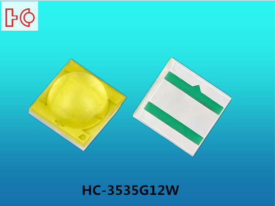
You might be seeking a high-performance LED solution or encountering questions during use. Today, let's discuss the 3535 ceramic LED lamp bead—a key component in many high-end lighting solutions. As Shenzhen Hengcai Electronics, specializing in manufacturing LED lamp beads, we deeply understand the importance of selecting and correctly using quality lamp beads. This article will provide an in-depth exploration of the 3535 ceramic LED lamp bead, guiding you on how to better utilize it to unlock its full potential.
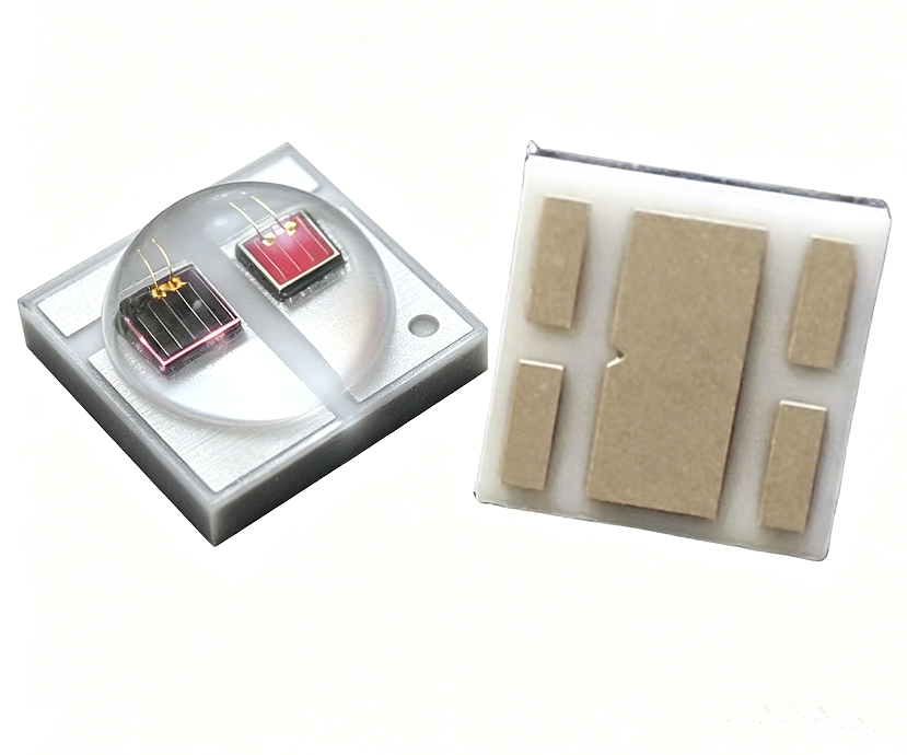
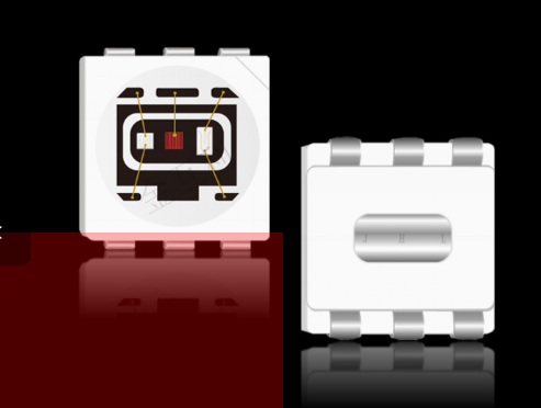
You may be familiar with LED lamp beads, but the term "3535 ceramic LED lamp bead" might sound distinctive. Simply put, it refers to an LED lighting device measuring 3.5mm × 3.5mm, with its most defining feature being the ceramic packaging technology.
Unlike traditional LED lamp beads often packaged in plastics (like PPA or EMC), ceramic materials offer superior thermal conductivity, high-temperature resistance, and UV aging resilience—advantages unattainable with plastics. This grants the 3535 ceramic lamp bead innate robustness, enabling stable operation under high-current, high-power conditions while delivering an extended lifespan. Designed as a "workhorse" in the LED arena, it excels in harsh environments and high-performance applications.
Key advantages of ceramic packaging:
· Thermal Management: Dissipates heat 5× faster than plastic packages, critical for high-power applications (e.g., stage lights, street lamps)
· Longevity: Withstands temperatures ≤150°C, reducing light decay by >30% compared to plastic alternatives
· Optical Precision: Ceramic substrates enable precise light control (120° beam angle) and high CRI (up to 90Ra) for vivid color rendering
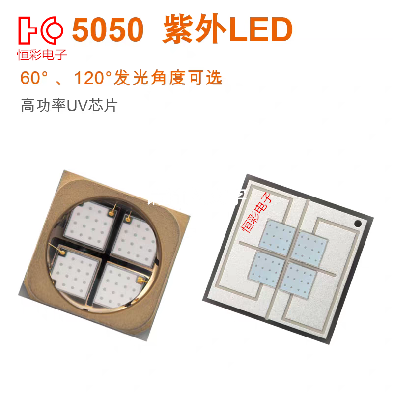
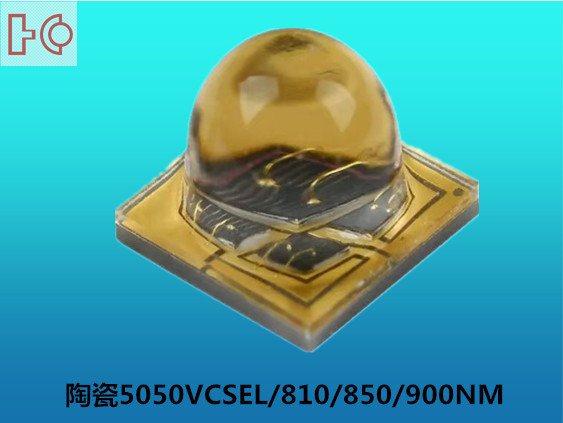
Technical applications include UV curing, PCB inspection, and architectural lighting where reliability is paramount.
Core Advantages of 3535 Ceramic LED Beads
Q: Why choose ceramic packaging? This technology unlocks the superior performance of 3535 ceramic LEDs through five key benefits:
1. Exceptional Thermal Management
Ceramic's thermal conductivity (24 W/m·K) far exceeds plastics like PPA/EMC25, rapidly dissipating heat from LED chips. Effective heat control minimizes luminous decay and extends operational lifespan.
2. High-Power Tolerance
Superior heat dissipation allows sustained operation at currents up to 1,500mA6, enabling brighter light output vital for high-intensity applications like stage lighting or automotive systems.
3. Extended Service Life
By reducing junction temperatures by 30-40% versus plastic packages, ceramic encapsulation slows material aging. This delivers lifespans exceeding 50,000 hours with <5% luminous decay.
4. Environmental Resilience
Ceramic resists UV radiation, humidity (IP67/IP68 rated)6, and extreme temperatures (-40°C to 150°C). This ensures stable performance in demanding environments like coastal lighting or industrial zones.
Compact & Versatile Design
The miniature 3.5mm×3.5mm footprint16 achieves high luminous flux density (up to 180 lm/W), enabling integration into space-constrained applications including medical devices and automotive lighting
Technical Reinforcement:
· Thermal conductivity of aluminum nitride (AlN) ceramic substrates reaches W/m·K, outperforming metal-core PCBs.
· Maintains >90% initial brightness after 2,000 hours in 85°C/85% RH conditions6.
· Supports wide voltage ranges (3-36V) and dual dimming modes (PWM/analog)6 for flexible system integration
Professional Guide to Maximizing 3535 Ceramic LED Performance
Q: How to correctly deploy 3535 ceramic LEDs for optimal results?
Simply powering them won’t unlock their full potential. Critical technical considerations include:
1. Thermal Management: The Decisive Factor
Effective heat dissipation directly dictates lifespan and luminous efficacy. Poor thermal design can degrade performance below conventional LEDs.
· Optimal Substrate Selection o Aluminum PCB: Cost-effective with moderate thermal conductivity (1-3 W/m·K), suitable for general applications. o Copper PCB: Superior conductivity (~400 W/m·K), ideal for high-power scenarios like stage lighting. Requires ≥2oz copper thickness. o Ceramic Substrate (Al₂O₃/AlN): Highest performance (24-180 W/m·K), near-matching CTE with LED chips. Mandatory for medical/automotive uses. · Thermal Interface Materials (TIMs) · Heat Sink Design o Fin density/orientation: Impacts natural convection efficiency. o Surface treatment: Anodic oxidation boosts radiation emissivity. o Active cooling: Fans required if ambient temperatures exceed 45°C. · Current Control: Drive at ≤700mA per chip (4W total for quad-die). Constant current drivers (e.g., PT4115) prevent thermal runaway. · Optical Alignment: Pair with secondary optics (lenses/reflectors) to achieve 15°–120° beam angles. Eliminates color deviation. For outdoor/industrial use: · Select IP65/IP68 encapsulated versions. · Avoid sulfur-rich environments to prevent silver plating corrosion.
Apply thermal grease/pads (≥8 W/m·K conductivity) between LED beads and substrates. A uniform thin-layer application minimizes thermal impedance. Excessive TIMs can hinder heat transfer.
Goal: Maintain junction temperature (Tj) ≤105°C (125°C absolute max).2. Electrical & Optical Optimization
3. Environmental Protection
Critical Implementation Checklist
Improper soldering (e.g., prolonged heating) cracks ceramic substrates. Use pulsed-heat tools with ≤3°C/sec ramp rates.
Pro Tip: Monitor Tj via forward voltage drop (Vf) shifts. A 10% increase indicates critical heat accumulation. By integrating these protocols, 3535 LEDs sustain >90% luminous flux after 10,000 hours—even in 85°C/85% RH environments. Technical Guidelines for 3535 Ceramic LED Implementation Electrical Parameters & Driving Protocol · Constant-Current Driving Essential o Critical Values: § Forward voltage: 3.0–3.6V (UV) 3 / 3.0–3.4V (white) § Recommended current: 700mA (3W) 5 to 1,500mA (5W) § Absolute max junction temp (Tj): 125°C · Driver Selection Criteria o Use ICs like SY7200AABC (30V input, 96% efficiency)1 or HV9910 (12V systems)4 for precise current control. o Avoid voltage-driven circuits – LED brightness correlates linearly with current. o Implement PWM dimming (≥1kHz) for intensity adjustment. Soldering & Assembly Protocol · Reflow Soldering Profile o Peak temperature: ≤260°C (exposure ≤5 seconds) o Ramp rate: ≤3°C/sec to prevent ceramic substrate cracking. · Manual Soldering Precautions o Iron temperature: <300°C with <3-second contact per pad. o Zero mechanical stress on lens or ceramic body. Critical Safeguards 1. ESD Protection o Operate on grounded surfaces using antistatic wrist straps. o Ceramic LEDs sustain damage at >1kV static discharge. 2. Thermal Runaway Prevention o Constant-current drivers (e.g., PT4115) mitigate overheating risks. o Monitor thermal derating: Reduce current by 4%/°C when Tj >105°C. Implementation Checklist
LEDs require stable current (not voltage) to maintain brightness and longevity. Voltage fluctuations as small as 5% can cause >50% current deviation, accelerating lumen depreciation or burnout8.
Pro Tip: For multi-LED arrays, match forward voltage bins within ±0.1V to prevent current imbalance. UV curing applications demand <5% current ripple to ensure polymer crosslinking uniformity.
Following these protocols ensures >80% lumen maintenance at 50,000 hours – critical for medical/industrial systems
Application Scenarios of 3535 Ceramic LED Beads
Leveraging their superior performance, 3535 ceramic LED beads are extensively applied in domains requiring high reliability, brightness, and longevity:
· Automotive Lighting: Headlights, fog lamps, and daytime running lights demand high luminance, robust durability, and vibration resistance
Plant Lighting: Growth lamps necessitate intense light density, specific spectral outputs, and stable long-term operation for horticultural applications.
· Outdoor Lighting: Street lamps, tunnel lights, floodlights, and spotlights require high brightness, extended lifespan, and weatherproof capabilities.
· Industrial Lighting: High-bay fixtures in factories and warehouses prioritize efficiency and continuous usage under harsh conditions.
· Medical Lighting: Surgical and endoscope illumination demands exceptional luminance and color rendering properties for precision diagnostics.
· Special Lighting: Stage, photography, and flashlight applications benefit from their versatile brightness and compact design.